Cummins 4BT & Diesel Conversions Forums banner

2004 Dodge Durango 4bt

43K views 105 replies 20 participants last post by  artemis8me  
#1 · (Edited)
It has begun. Project Vehicle is a 2004 Dodge Durango SLT 4x4. It has 92,000 miles and a siezed hemi. Hemi-ectomy is underway. The current plan is to use a 47RH or RE with a 4bt and the existing transfer case.

I still need to purchase the transmission, electric vacuum pump
intercooler, otherwise all hard parts are acquired. I have numerous 6bt parts from a 53 block removed from my 99 Ram so i plan to set up the front of the engine similar to the dodge 6bt, dodge alternator, belt routing and ac compressor location etc.

Next steps:
Hemi-ectomy - there is very little room around bell housing, a real challenge to remove, plus engine is siezed so i am going to attempt to leave TC on engine when i pull since i can't spin crank to separate flex plate from TC, could be messy.
Motor mounts - have 6bt mounts, not sure if they will be part of the solution or not, current hemi mounts to the frame and IFS mount seem simple and could be part of the solution too.
Oil pan - plan to make a 4bt/hemi oil pan hybrid, space between front diff and pan is tight
Intercooler install - not sure what intercooler to use, or where it will be located exactly, i am sure i will be inspired at the time
Tachometer - plan to use hemi crank sensor and mount tone ring on damper, not sure if i will need cam sensor or not
Temp sensor - hemi temp sensor mounted in 4bt
Oil pressure switch - hemi oil pressure switch
 

Attachments

  • Like
Reactions: artemis8me
#36 ·
No progress since last spring, but we've finally gotten moved into the new shop, with 2 post hoist, so I hope to have some progress to pay in the next few weeks

Next topics to address, left side motor mount, Cummins starter install and differential install
 
#38 ·
Back in Action

Well, we are back in action, durango on the hoist and tackling the starter/engine mount interference issue. Top ear of engine mount has been removed, starter now has clearance, will need to manufacture a front right mount to replace this mounting point.

 
#39 · (Edited)
Mocking up right hand mount. I drilled a 3/8" piece of plate to mount to the block, and cut up the original hemi mount to mate to it, please forgive the spot welding, I did most of it out of sight with a mirror. I will remove the top green support once the mount angle has been supported.

 
#40 ·
Right hand mount complete. Left hand front mount is in progress, utilizing the front motor mount from the bread truck application, and the Ferd 300-6cyl motor mount, planning to put support directly below to the front suspension cross-member. After moving engine forward slightly, the block skirt on the RH side is quite close to the motor mount even after trimming back the face of the motor mount. I am planning to trim the block skirt slightly to accomodate.

 
#42 ·
Today was devoted to motor mounts. RH Mount complete.


LH Mount nearing completion, need to paint, then complete.


The engine is now sitting completely on its own mounts. With the sway bar lowered, the oil pan will need very little modification to clear the differential. I am planning on a front sump arrangement. I am not sure if I will trim the aluminum fins on the diff, or shape the oil pan slightly or both.
 
#44 ·
Lookin good. When I did the Dakota I used the front motor mount locations also, and hung the differential from the mid mounts also.
This model has a brace that goes from the top of the diff to the engine I am assuming to take out sway or wobble of the diff, How much does the diff move, should i consider re-bracing? I would have to anchor it to somewhere near the starter. Not impossible, just a pain. Your thoughts?
 
#48 ·
That brace is very important. If you ever intend on using the 4x4 the differential will want to rotate and that differential is cast aluminum and will crack very easily.
Thanks for the advice, I assumed I should but needed that practical advice, that side is very tight with the dodge/cummins adapter and starter. Once I have removed the engine again I will make some kind of strap to something, just not sure what so far.
 
#47 ·
On my 02 ram thread, I used the stock engine mounts for my 4bt, I kept the stock driver side and I ended up stupidly trashing my passenger side mount. I also plan to somehow make a mount on the trans to the diff, so its all pretty solid. Oh and the replacement engine mount/bushings, for me was around 130 bucks! But I had to, mine are junk, replacements are made of steel, so a bit more heavy duty was nice.
 
#50 ·
After a little heating and flattening, I was able to get the oil pan in without any cutting, this is the front view.


I heated the radius of the pan near the back and lightly tapped it, flattening it about a quarter inch, this is the view down the left hand side from the front.


I will still have to do a small amount of additional flattening, the pan appears to be slightly engaging two of the differential fins, I will grind these down as much as I dare when the engine is out.


I have two oil pickups, one a 4bt rear sump pickup and a 6bt rear sump pickup, I plan to do some cutting and welding and make a front sump pickup. If that fails I will have to purchase a front sump cummins oil pickup.
 
#51 ·
The heating on the oil pan has lifted the paint coating on the inside of the oil pan, do I need to repaint or just sand off around the burnt area for flaking, any thoughts?
 
#53 ·
I decided to use the rear sump pickup from a 5.9 dodge, I had to shorten its length, re-attach a side brace and shorten its drop tube by about 1/2" to keep it from touching the bottom of the pan.


I continued heating and flattening the oil pan, I now have about 1/2" clearance to the differential fins in most places.


Next step, I need to begin modifying the timing case cover to accept the hemi camshaft tone ring and the cam position sensor. Also I need to manufacture a bracket to hold the crank sensor to the cummins flywheel.
 
#56 · (Edited)
Cam Tone Ring

Installed on the injector pump gear, turns the same direction as the crank just like the hemi. I welded a 1-1/4" washer on the front of the tone ring and a 3/4" behind the first washer. I drilled one small hole to the side of center and used a M8 bolt to keep the tone ring aligned. I believe the threaded hole in the injector gear is for pulling the gear off the injector pump.


#57 ·
Airbox Help

I would prefer to use the factory airbox, I am just too close to the dodge/cummins alternator. I have the alternator in the furthest up position but it still won't clear.


There is not a lot of room in that corner. Has anyone cut and plastic welded their airbox? any other ideas? any suggestions on aftermarket air cleaners?
 
#58 ·
Digital PRNDL Gear Indicator - Minor Breakthrough!

The story is far from over, but I have spent 3 days off and on trying understand the circuitry and hardware in the 545RFE to get a Neutral or Park signal to the PCM ECM to allow for the start circuit to fire. Today we were successful in grounding combinations of those wires in the harness to tell the ECM which gear we were in.

In a 545 RFE there are 5 electrical contacts attached to the valve body shift assembly that in specific grounding combinations provide the PRND21 signal to the PCM and move the gear indicator light.

P 1-2-5
R 2
N 1-2-3
D 3-4

This is what I am going to attempt. I am going to have a DPDT relay that when NC, it will ground 3 - 4 and produce a Drive signal. When that solenoid is grounded by the 47RH Park/Neutral/Reverse Switch, it will throw the solendoid to allow one of the 3 other individual SPST solenoids to fire, depending on which ground (Park/Reverse/Neutral) is grounded.

I will need to use diodes to keep the ground from the shared terminals from backfeeding and grounding unwanted terminals. I am going to contact a friend from Minnesota who is an electronics guy and see if he might be able to mock this up on a circuit board and save me a big clunky relay and wire mess.

Let me know your thoughts. Has anyone had success doing this before?
 
#59 ·
Radiator Rough Fit

I placed the radiator and condensor rads, pretty clean fit, no issues for clearance. I will need to find an electric push fan and front mount the cooling fan. The top radiator hose fitting is angled away from the top coolant port on the engine. Does anyone have a resource for rad hoses other than a treasure hunt to the auto store?

 
#60 ·
I had to modify my original shift translator design. The P N R switch on the 47RH only has two signals, not three. It grounds the center terminal when in either park or neutral, and it connects the two outer terminals for reverse. I have been able to modify my switch box and I can get R and D to display on the digital display, I have not been successful in getting either a P or N to appear, however transfer case will shift normally, "scv drivetrain" light is now out.
 
#61 ·
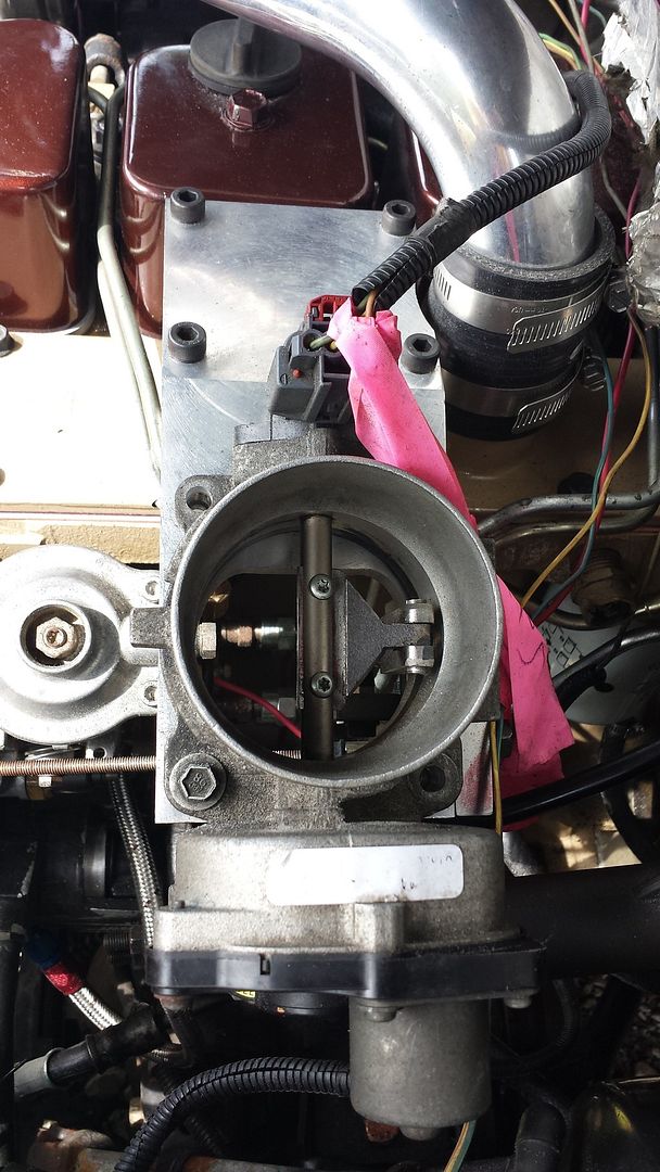
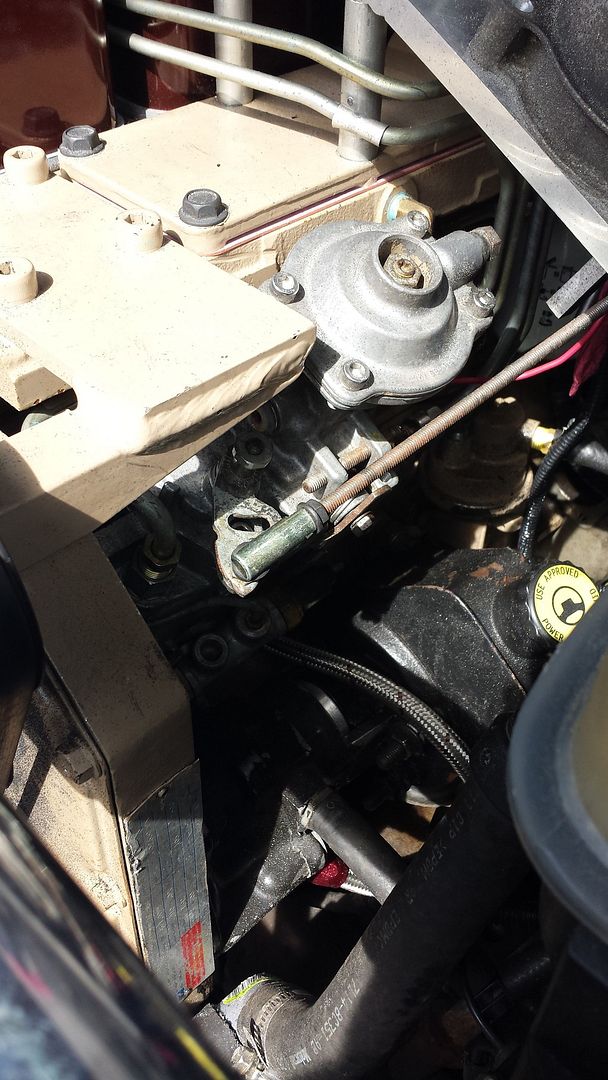
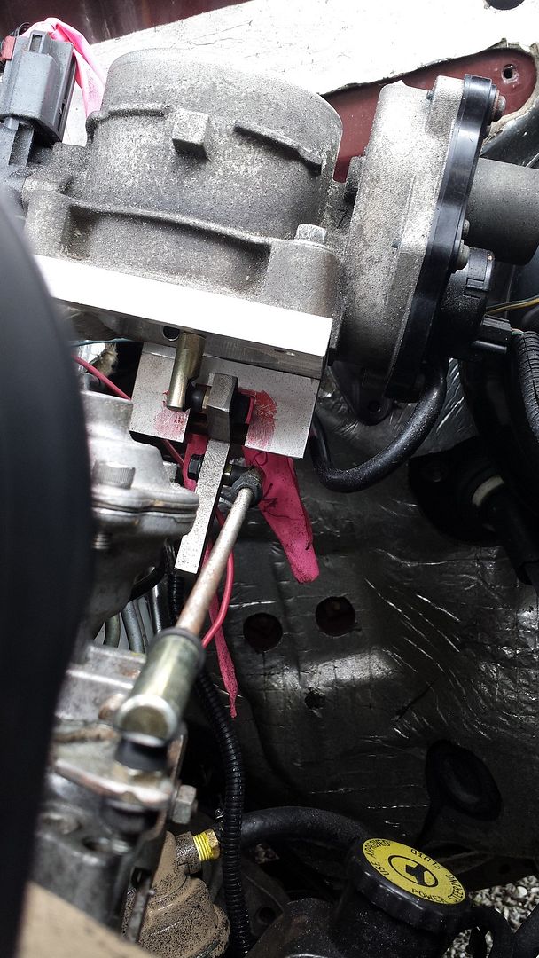
dont know if this helps or not on your throttle, but heres what I did on my 07 ford expedition.


Im having some other electrical difficulties, but I think once they are ironed out this should allow me to utilize the factory cruise, and hopefully some day a high idle control. I have no throttle return spring on the IP. I have very good throttle control. Idle adjustment is also easy as well. utilizing factory TPS as well.
 
#62 ·
dont know if this helps or not on your throttle, but heres what I did on my 07 ford expedition.

Im having some other electrical difficulties, but I think once they are ironed out this should allow me to utilize the factory cruise, and hopefully some day a high idle control. I have no throttle return spring on the IP. I have very good throttle control. Idle adjustment is also easy as well. utilizing factory TPS as well.
I had a similar thought especially about getting the factory cruise to work since it is contained in the ECM, I have hooked up the hemi throttle body to the wiring harness, it flutters when i cycle the key, but it does not open when the pedal is pushed. The engine is not running during the test so I don't know if that matters but, once I fire it I will see if a tach and cam signal will let the TB cycle with the foot feed. If it will, this is a great way to use existing controls. Thanks for the input.
 
#63 · (Edited)
Yea I'm not real familiar with how the dodge stuff works. Are you sure the necessary stuff is hooked up for it to function. On.my ford it was plug and play. I do not have any cam or crank speed inputs yet. I machined my balanced for the crank sensor to read from but still no tach. My guess is there's something that needs plugged in for your butterfly to work. I think you should put effort in on getting the stock throttle body to work to pave the way for others that do newer conversions. The only quirk my system has is that whenever you touch the throttle and let off it actually takes it below your set idle and then instantly brings it back up. So...on the original gasser it would actually completely close the throttle body and then reset to idle. Does that make sense?? So if I'm in neutral and give it say a measly 5% throttle increase and then let off it will take engine rpm below idle speed and then back to idle all in a split second. Mines a stick and I don't notice it banging through the gears. If you got any questions or concerns let me know. Some people thought I was crazy for taking my injection pump throttle return spring off but after much testing the ford throttle body has plenty of torque going in both directions. If you need anything machined let me know.

On edit just looked at pics of the dodge throttle body and I didn't notice the TPS sensor on it. Where is your TPS located?? My ford one is on the throttle body. It has the drive by wire wires and also the throttle position sensor on the opposite side of the electric motor. In order for my throttle body to work my TPS has to be plugged in.
 
#64 ·
I think the tps is integrated into the throttle body and motor assembly unless the computer uses the sensor on the footfeed, not sure. Every sensor is plugged in, i am wondering if the butterfly wont open unless the computer thinks the engine is running.
 
#65 ·
Project resumed, never thought this project would take me 4 years, since there is snow on the ground, I'm back in the shop.

Next is the AC compressor mount. I had originally thought clearances were too tight to use the Dodge Cummins factory mount, but thankfully there is no interference. With all the accessory drives in place, next thing is the airbox. In factory position, the air outlet strikes the dodge/cummins alternator.


With some modification, I think I can use the hemi airbox. I cut and lowered the mounting tab and rotated the airbox slightly. I will have to fasten the side near the rad to the rad somehow. The hemi air duct should also work, the extra air plenum manifold was cut off and plugged with an ABS plumbing plug and some epoxy. With the help of a 3.5 to 3 inch reducer and some 3 inch exhaust pipe fresh air will reach the turbo inlet.


#66 ·
In my 03 ram I took the stock TB, stuck it on the back driver side of the block, and Used a Coupler nut and a cap bolt, cut the head off and made a adjustable length rod which connects to IP arm. It opens and closes completely and uses the stock TB throttle cable arm which I mounted to the IP throttle lever. Haven`t drove the truck just yet, but I`m off for 2 weeks for Christmas and New years shut down, plan to get some real work done then. I doubt the hemi and 4.7 are to far apart, I know my air box according to S&B uses the same filter up to the 8L V10 dodge had. So our boxes should flow plenty of air.