Cummins 4BT & Diesel Conversions Forums banner

1955 Brockway 155W Continental to Cummins Conversion

26K views 108 replies 11 participants last post by  speedfreak440  
#1 ·
I’m sure most folks here are not familiar with Brockway trucks, but they were manufactured in Cortland NY from 1912 to 1977. They were bought by Mack in the mid 50’s and were an ‘autonomous’ company until the day they closed in 1977. They have a very loyal following and there is an annual truck show dedicated to Brockway’s the second Saturday of every August.

My Dad drive truck for a living and always had an interest in Brockways. I bought my 1955 155W in 2000 and spent 8 years restoring it. In 2008 we drove the truck for the first time from near Scranton PA to Cortland NY for the annual show. I So far I have put a little over 7300 miles on it. Even with having 2 other Brockways, a 361 and 761, I really enjoy driving this truck. So I decided it was time to make a few changes...

This forum has been very helpful with some issues I ran across with my Cummins 6BT so I figured I would share my build thread here. This starts in the fall of 2015...

Image


The 42BD or 427 flathead Continental has been a great motor but really doesn’t have the power you need for today’s roads. It will run 55mph all day long on level road but once you hit any kind of grade your down to 40 in the right hand lane with the 4 ways on. I would like to be able to run 60 mph up a hill so I decided it would be a good time to upgrade the Continental. I did consider making some upgrades to the 427, like adding dual carbs with the Ellis manifold, maybe an MSD ignition, a Mallory distributor, etc., but most of these upgrades would have little gains verses the costs. It’s also start to leak some oil so that was another deciding factor...

So after much thought I decided to replace the Continental with a 5.9 Cummins. They are comparable in size as well as weight. I did consider the 8.3 Cummins but that weighs in at 1800lbs which is about a 1000lbs heavier than the Continental. You can also build decent power fairly economically with these motors. I also knew that these were used in some smaller Freightliners with air brakes so that was a plus since (air compressor, etc...)

More to follow...
 
#77 ·
Then I dug out the exhaust brake I bought a while back. I wound up buying a complete kit for a 94-98 Dodge pickup, complete with the air compressor, tank, flanges, etc. They had a $250 rebate on the entire package so it was cheaper to buy the whole kit instead of the individual pieces. The unit I used was a PacBrake #44060 along with 4” inline mounting flanges #11400...

Image


I lined up the upper flange and welded it to my downpipe. The inline flanges are stainless but weld fine to the steel pipe...

Image


Once the exhaust brake was bolted in place I moved on to the next pipe. But there is some history with this pipe... I needed a long sweep to help me clear the front axle and tie bar. I had this pipe that came from my Dad’s 361. It was probably the only new piece on the truck when he bought it. It came from under the truck, behind the fuel tank and into the bottom of the muffler. If I remember correctly, the sticker was still on it when we brought the truck home. But it sure looked like it would work perfectly for my truck!!!

Image


I wound up cutting the 45 bend off and adding 2” to the long side of the sweep, and then adding the bottom exhaust brake flange on it...

Image


After I welded it we installed it to see how everything lined up...

Image


Well that’s it for now!
 
#78 ·
Dang, this thing is just mind bending. When you were installing the IP and compressor, you quickly found the oil line and fitting has to go in first. Actually, I believe the compressor is the last piece of the puzzle to install. An interesting item is I have a factory HX40W cast iron exhaust elbow that looks much like the one you made out of pipe. It might have saved you a lot of fabricating. If I can dig it up I'll post a photo. On it, you could have probably mounted the exhaust brake to it and then continued with pipe. Did you consider using a section of stainless flex pipe in the setup? Would help relieve some of the engine vibration. By the way, that fan shroud is a work of art.
 
#79 ·
Thanks char1355... I'll address your concerns about the stainless flex in an upcoming post. Also, thanks for the comment on the fan shroud. I made one for the 671 Detroit in my Dad's Brockway since his was rusted out beyond repair. I used the same type of design here on my Brockway...

When we last left off we were working on the exhaust. After the exhaust brake was installed I ordered a 5” stainless flex coupling from Vibrant. I have used these on all of my builds and have been very happy with them.

Image


At this point, I used the 90 degree 4” elbow from my Dad’s 238, and then bumped up to 5” with a 4 to 5” adapter from Napa and then the flex piece. After all the pieces were cut to length I welded them in place and them trail fit them.

Image


For the muffler I decided to use the 5” MBRP SS one I originally bought for my Dad’s 361. After the exhaust was done, I decided to work on the oil drain tube for the turbo. I had several tubes to work with but none of them were exactly what I needed. I also tried one of those flexible drain tubes but the longest one they made was too short. After some thought I decided to make my own by cutting up a few of the ones I had...

Image


I wound up using the flange from the turbo that came with the motor and then a 90 degree bend from one that came off of a Dodge pickup...

Image


I welded one piece at a time and was able to deburr the inside of the weld as well. When all was said and done I wound up with this...

Image


After a trial fit on the motor I connected it to the drain tube in the block with a piece of 7/8” high heat braided hose that was specifically made for turbo drains. I had also bought this for my Dad’s truck but went a different route at the time.

Image


If you remember a while back I installed a Ross TE66 steering box on the truck from my 58 parts truck. When I painted the motor red, I also painted an extra drag link I had. The original one was heavily pitted. It was still in good shape structurally, but I figured I might was well replace it since I had a better one. One of the cups was fairly wore and someone had shimmed it with a washer, so I decided to remove the one from the 58 parts truck. The cups were in great shape although both springs were broke. My original springs were still in good shape so I reused those...

Image


After cleaning everything up, I started reassembling the pieces...

Image


At that point we adjusted the steering box as per the International instructional manual I posted earlier in this thread. I had to remove a few shims under the 4 bolt flange to get the preload set correctly on the bearings (they were too loose...). Once that was done we set the final adjustment on the side screw. We’ll see how well it works once we start moving it out of the garage!!! On a side note, this box has about 7.25 turns lock to lock. All that’s left to do now is top off the corn head grease and install a new vent in the fill plug hole.

More to follow...
 
#80 ·
The exhaust brake only came with a throttle switch and the instructions noted that a clutch switch was optional. Since I used the original microswitch from my Dad’s 671 jake on the throttle, I decided to use their supplied throttle switch for my clutch. Basically they’re all the same type of switch...

Image


I removed the bracket that came on the switch and made a new one from aluminum that would bolt to the floor...

Image


In the first pic with the switch you can see a diode that runs from the switch to the metal bracket. This diode is used to prevent arcing within the contacts. So after I installed the clutch switch, I added a 1N4004 diode to the throttle switch. These are only a few cents each and I believe you can still get them at Radio Shack.

Then I moved over to the battery box. I had a small battery in it that I wound up borrowing from my ’86 442. I wound up killing the Optima battery a few years back and could never bring it back. So in a pinch I grabbed the one from my car and surprisingly enough it spun that Continental over with no issues at all. If fact it never even hesitated. But I knew the Cummins was going to need a bigger battery, maybe even 2 in parallel. But first I need to fix and add a few things within the box.

For my water to air aftercooler setup, I needed to provide power to (2) 7” fans along with an electric water pump. But I also needed to run a new #4 wire from the disconnect switch to the alternator since the one from the Continental was too short. So I decided to repurpose the original alternator wire to power the fans and water pump. To do that, I added another maxifuse in the battery box and located it next to the original one that serves the fuse box. I prefer these maxifuses over fusible links.

To power the new Fass fuel pump, I needed to pull power directly from the battery. The pump came with a relay and a fuse so I wound up using the wire from my original Carter gas fuel pump to control the Fass relay. I had room in the batter box so I mounted the new Maxifuse holder, Fass relay and Fass fuse in the box on 1/4" pieces of aluminum. I drilled and tapped the aluminum with 10x32 bolts but uses 3M double faced tape to fasten the aluminum to the battery box. I didn’t want to drill holes in the battery box...

Image


And the finished product (with the small battery...)

Image


At this point I picked up a larger group 65 battery and made a new hold down for it...

Image


Image


But while I was at it I decided to replace the Cole Hersee disconnect switch with a Flaming River. The Cole Hersee switch is rated for 100A while the Flaming River is rated at 250A and made in the USA.

Image


At the end of the day here is what I wound up with, a new battery, new disconnect switch, additional fuse, and the Fass relay and fuse. I also added a plug for a Battery Tender as well...

Image


More to follow...
 
#81 ·
One of the issues I spent some time trying to figure out was how I was going to connect the fuel supply and return lines to the existing fuel tanks without drilling, cutting or welding them. These tanks are 44 gallons each and are original Synder tanks. They actually came off the 154W Marionelli parts. My original tanks were in very rough shape and were rusted through behind the Synder tag and somebody patched them with fiberglass. These tanks have a 3/8” connection for the fuel supply which is located on the top of the tank. This 3/8” then runs internally to the bottom of the tank.

The Fass system requires a #10 (1/2” supply) and (2) returns, (1) #8 (1/2”) directly from the pump and (1) #6 (3/8”) from the P7100 injection pump and injectors. After some thought, I figured I could use the 1/2" NPT drain plug on the bottom for my #10 supply. For the returns, I decided to make a new plate that would fit where the existing sending unit is located.

I started with partially drilling a 2 3/4" hole through a 1/4" piece of steel. I didn’t drill through it all the way at first since it made it easier to hold in the vice and milling machine...

Image


Then I came up with a sketch to see if I could fit the (2) return lines along with the original fuel sending unit...

Image


Once I was confident everything would fit, I drilled the (5) mounting holes, the (2) return line holes as well as a hex hole for the sending unit wire. This was done by drilling a small hole and then using a small file...

Image


The hole in the dead center is 1/4" and this was from the hole saw. Once the holes were drilled I finished the 2 3/4” hole and turned it in the lathe using a bolt mounted in the center hole. I then took the #6 and #8 steel AN fittings I picked up from Napa and turned them down as well in the lathe...

Image


Image


After I was done with the fittings we did a quick trial fit in the tank...

Image


Once I was confident everything would fit, I had the fittings tig welded to the plate. I also plug welded a 1/4" stud in the center hole of the plate...

Image


Image


I painted it with gray hammer tone paint that is a very close match to the color of my fuel caps, which happen to be the same color I used for the Continental.

More to follow...
 
#82 ·
About a week later I modified the bottom of the fuel sending unit to clear the return line holes and bolted it to the new plate. I also mounted the sending unit wire as well...

Image


Image


After I installed the plate I connected the return lines using some low profile 90’s from Earls...

Image


That’s it for now!!!
 
#83 ·
If you remember a while back I installed (3) Isspro gauges in the upper package tray (just below the headliner.) I installed a pyrometer, air intake temp gauge and fuel pressure gauge. Stan, you reminded me to make sure I welded a bung in my downtube for the for the pyrometer thermocouple. On these motors, they recommend installed it directly in the exhaust manifold before the turbo. Brandon also brought this up when I was asking where to put the thermocouple in my Dad’s truck. The new BD exhaust manifold I bought comes predrilled and tapped for (2) pyrometers. So I installed the thermocouple in in the manifold and ran the wires in the cab and up the passenger side pillar (fun fun fun...)

The Fass fuel pump comes with a 1/8” NPT port for a fuel pressure sending up so I also installed that sending unit. The last sending unit I needed to install was for the air intake temperature gauge. I mounted this directly in the intake plate in an existing hole that had a pipe plug in it.

The port was 1/2" NPT and the fitting was 1/8” NPT. I found a brass reducer and would up drilling the inside out to create some room for the sending unit...


I realize these are small details, but details regardless...

At this point I ran both the fuel pressure and air intake wires up the pillar on the drivers side. The gauges are meant to have their wiring piggy backed together but I made my splices on top since I was getting tight on space with the air wiper unit. To help with the wiring, I used to screws to hold the panel in place...


And then I straightened everything up and reinstalled the panel...


At that point I had to connect one last wire under the dash and this was for the lights in the gauges. I connected this to the back of the tachometer light stud and called it a day...

More to follow...
 
#84 ·
One big item I needed to tackle was finishing up my clutch and throwout bearing spacer. When I installed the trans with my spacer, I quickly realized it was a little too long. I sure beats being a little too short! So I had to remove the trans so I could shorten the spacer. I made a jig for the 4 wheeler jack and had to cut a section out of the 1” angle frame I made to support the wood floor. This would give me room to slide the trans back. We also had to remove the entire clutch pedal bracket as well. I also made 4” alignment studs to help with reinstalling the trans...

Image


Image


After several more measurements I realized I needed to shorten the spacer up by 1/8”. So I pressed the throwout bearing off of it and removed the original collar. The back in the lathe it went...

Image


When I was done turning it I drilled (2) holes, on the top and bottom and tapped them for 1/4x20 set screws. Although it’s a press fit, these screws will help keep the spacer in place and are good insurance (belts and suspenders...)

Image


And then we pressed everything back together...

Image


Once I had it back in the trans and slid the trans into the motor, I realized the return spring was not pulling everything back far enough and the bearing was still touching the clutch fingers. I thought the original spring was weak so I picked up a handful of other springs to try...

Image


More to follow...
 
#85 ·
After several attempts I realized the collar was catching on the shaft. Very slightly, but just enough to keep it from returning the last 1/4”. So I cleaned the shaft with some light sandpaper and took a thousandth off the inside of the collar I made. This seemed to do the trick so we installed the trans and finally bolted it in place.

The original clevises were wore so I ordered (2) new ones from McMaster Carr along with a piece of 3/8x24 threaded rod. I cut the rod to length, installed the new clevises and then we adjusted the clutch. I also decided to replace the trans fluid at this point. The trans was dripping from the drain plug as well as the bolts that held the PTO cover plate on. I knew the threads for the drain plug were not right. I had a 3/4" NPT tap in my collection now so I cleaned up the threads and installed a new drain plug. I also resealed the PT cover, this time with a new gasket and gray “Right Stuff” from Napa which comes in a tube that you use in a caulking gun. I also picked up a 5 gallon pale of 90W mineral oil from Napa. This is a 5A430 trans and takes 8 quarts of fluid as per the factory manual.

I had the week off between Christmas and New Years and I had a laundry list of items I wanted to tackle. First I started with the injection lines...

Image


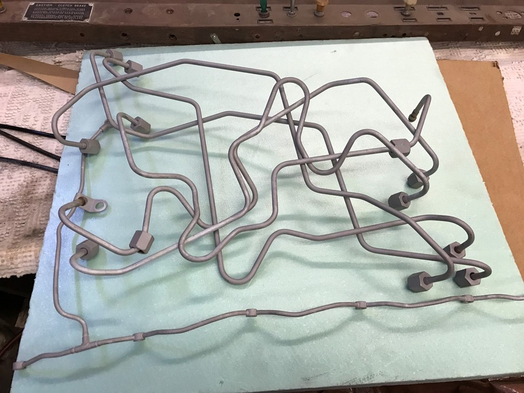
I thought about replacing these but they were in good shape and new ones are $$$. They only go together one way and the isolation mounts are import because they prevent them from cracking. I drew a diagram of all the lines and took one apart at a time. I used the old injectors covered with Gorilla tape to plug the ends and then used glass beads in my cabinet to clean each one...

Image


Image


I also blasted the individual brackets and soaked the plastic spaces to try to remove to old tan paints...

Image


I primed and painted each line and them set them off to the side. The next item was to install the new injectors I received from Industrial Injection. I wanted to spin the motor over to get oil pressure before installing the injectors. We couldn’t get any oil pressure and discovered the oil pump did not have a prime (based on several articles I read on line...) Some folks pressurize the oil feed through the oil sending unit line using oil in a pressurized container. After some thought, I dug out a spare fuel pump from my Dad’s 671 and sucked new oil through the pump and into the filter housing using a socket attached to a cordless drill to spin the pump. After pushing a quart of oil through with the fuel pump we reconnected the oil pressure gauge and spun the motor with the starter. Now we had oil pressure!!!

Once we were comfortable that we had oil throughout the motor we started installing the injectors...

Image


That’s it for now!!!
 
#86 ·
After the injectors were installed I installed the injection lines. I blew carb cleaner through each one just as a final measure and then blew compressed air through each. The paint didn’t react well to the carb cleaner so it looks like I will have to revisit that in the future.

Now that the trans was back in I felt I could reinstall the floor for the last time (hopefully!!!). I welded tabs to the floor brace I took out and then bolted it in place. Now if for some reason I need to take the trans back out, I can remove the wood floor and take this section of brace out.

Image


At that point I needed some help holding the bolts in place so Maddie came out and helped me...

Image


We also discovered that wire ties work well for pony tails!!!

Image


After much research and measuring I decided to go with a Type 14 air to water aftercooler from FrozenBoost.com. To help make the decision, I made a cardboard pattern to see what would work best. Option 1 had the inlet on the top while option 2 had the inlet in the front. In either case, the outlet was on the bottom. Most people lay these on their side due to hood clearance. But in my application, I could stand it straight up...

Image


At first I thought I would be able to use the factory 90 air intake elbow but soon realized it just wasn’t going to work. Unfortunately these are not square and you can only rotate them 180 degrees, not 90... A while back I bought the turbo spacers from a place called Mayhem Metal Works. They also sold aluminum flanges to make your own intake horns with 3” holes. I bought one of these along with a 3” aluminum tube joiner. I cut the bead off of one side of the joiner and then had it tig welded to the flange...

Image


I then mocked up both the new air intake horn along with the intercooler...

Image


Image


More to follow...
 
#87 ·
The original turbo came with a cast aluminum 90 so I cleaned it up and decided to use it since it fit my S300 turbo...

Image


Image


To connect the turbo to the intercooler, I used (2) 3” 90’s along with a piece of 3” aluminum tubing. And here is a good ‘aerial’ shot of everything installed along with the clamps...

Image


Once I was happy with the location and fit of the aftercooler I made (2) support brackets, one for the front and one for the top...

Image


Image


It’s hard to see the top bracket, but you can see the front one in this pic. I can’t make one for the back due to the injection line clamps. If it fairly rigid with the two support brackets but not too rigid...

Image


The next item on the list was the air filter. The original turbo had a rubber cobrahead on it, similar to this one from intakehoses.com...

Image


It turned out that it just cleared my upper water neck so I decided to use it. I also bought a 4” silicone 90 along with a 4” joiner pipe. At this point I started researching air filters. Most of the Dodge truck folks upgrade to what they call a BHAF or big honking air filters. I looked at (2) different Napa filters, both the FIL 6637 which is 8.5" x 12.38" x 4" and the FIL 2790 which is 10.5" x 11.8" x 4". With the cobra head and the 90, it turned out the 6637 was going to fit the best. Napa had these in stock so I picked one up to trial fit it...

Image


That’s it for now...
 
#88 ·
I think I'm having enjoyment overload. One note. You mentioned that the new exhaust manifold had 2 ports for the EGT sensor. Actually one is for EGT and the second is probably for back pressure. Isspro is one of the few companies who offers that gauge in their line up. You can do one quite a bit cheaper by using a mechanical boost gauge. You run a coil of copper or stainless tubing out of the manifold to a small particle filter and then on from there to the gauge. Just have to be careful as that is a CO source inside the vehicle. The expensive one from Isspro is all electric. You might have been able to get a flex turbo drain to fit your need. Cummins has several of those and one designed for a top mounted turbo is part # 3934091 which appears to be pretty darn long. Nothing wrong with what you have.
 
#90 ·
Thanks for everyone's comments!

char1355... I did try a long flex oil drain tube but it was still too short so I decided to make my own...

Well it’s time for another update... We have a few big ‘things’ left to finish the conversion, well at least before we start the motor... These include the fuel lines from the tanks and the radiator for the aftercooler. So we’ll start with the fuel lines...

As I mentioned before, by using the FASS fuel system, I needed a total of (3) fuel lines, including a #6 return, a #8 return and a #10 supply from the tank. Since I already finished the return lines, I needed to figure out the #10 supply line. I couldn’t use the original supply line from the tank since it was only #6 or 3/8”. But each tank did have a 1/2" NPT drain that was on the bottom. The 1/2” NPT would allow me to install a 90 deg fitting but the problem was that it was towards the front of the tank, about 2” from the front of the tank. I was worried that if I hit something in the road it would tear the fitting out of the tank. Stuff happens, right? So I didn’t want to create a problem. And I still had to figure out a way to connect both fuel tanks to the fuel pump...

After much thought, I came up with the idea of building a fuel cross over bar, similar to the one on our 361 and 761. Those bars are made out of 2” square tubing and I had some 1 3/4" left over from the stand I made for the Continental a number of years ago. But I also wanted to hang some type of flaps to protect the bottom of the tanks from being sand blasted. I decided to make a bar that went from the outside of the driver tank to the outside of the passenger tank. I could use the bar to hang the flaps and mount the 1/2” #10 fuel line. Of course it wouldn’t be as easy as a straight bar since my exhaust was in the way.

This is what I had in mind..

Image


So I started by making a cardboard pattern with some miter cuts...

Image


After I was comfortable with the all the dimensions (making sure it would clear the exhaust, etc), I started cutting the square tubing with the hydraulic saw...

Image


Image


Once the cuts were done I beveled the edges in order to get everything ready for welding...

Image


After everything was clamped down I started welding everything in place...

Image


More to follow...
 
#91 ·
I kept the ends long and then trial fit it in place. I wanted to center it on the exhaust and them trim the ends...

Image


Image


On a side note, even though the bar hangs down it is still fairly high and I shouldn’t have any clearance issues In fact the lowest part is still higher that my Dad’s 361 so I should be in good shape.

Once I marked and cut the edges to length, I dug out the pieces of the flaps I cut off from the flaps I put on my Dad’s truck. These are the flaps that Dane sell and I really like the quality, very heavy duty. I had 14” stainless weights that my Dad bought me many years ago, so I dug them out and then cut the flaps to length...

Image


Image


My original through was to hang the flap from the bottom of the bar, but I wasn’t sold on it. The bottom of the fender stops right at the bottom of the tank, and I figured my bar would get sand blasted. And a 1 3/4" bar along with a 2” angle to mount the flap would be too much of a red painted surface. So I decided to mount the flap on the front of the bar...

In the meantime I fabricated the brackets that would mount the bar in place. I used 2” x 3/16” angle and drilled 3/4” holes so that I could bolt it to the fuel tank mounts. Once the brackets were done I welded them to the bar...

Image


In lieu of welding nuts to the bar to hold the flaps, I decided to use 5/16x18 rivnuts from McMaster Carr. I bought steel ones since I was worried about thread issues using aluminum ones. We started by drill the holes...

Image


And then installed the rivnuts...

Image


Image


And this is what I was after...

Image


More to follow...
 
#92 ·
Before I reinstalled the bar I assembled the 90’s along with 1/4 turn ball valve so that I could isolate the tanks. I will be shortening the handles on these valves but for now this is where I’m at...

Image


Image


I reinstalled the bar on the truck one more time and in this pic you can just see the top of the 90 degree fitting...

Image


At that point I marked the bar and drilled 1/4" holes to mount isolation clamps to hold the #10 line. Then the bar went back on again and was able to cut the Aeroquip lines to length and install fittings on each end. Basically I have both tanks to a T fitting and the T fitting is then run to the supply side of the fuel pump. And here is the finished products...

Image


Well that’s it for now!!!
 
#93 ·
Well we’re getting pretty close to starting this thing up! As luck would have it I found a guy 10 minutes from where I work that just started power and ceramic coating. He did a set of mid 30’s Ford wire wheels for a guy I work with and they came out great so I gave him a call to talk about my project. I wanted to have the exhaust ceramic coated but then figured I would also get a price from him to black powder coat to other parts I had. Then I wouldn’t have to take a bunch of things apart in the spring to paint them. So I wound up removing all the exhaust I made as well as a handful of brackets for the aftercooler, fuel pump. I also removed the radiator shroud I made...

Image


I dropped the parts of and a week later I was able to pick up the power coated pieces (the ceramic exhaust pieces would take a bit longer...)

Image


I also had the upper and lower water necks done. Once of the nice things about having them powder coated is that both the inside and outside gets coated. My original ones were started to rust on the inside...

Image


The original water neck studs were pretty tired so I decided to make (4) new ones from the extra treaded rod I bought for my clutch linkage. I also made new cork gaskets. The thin black gasket material typically I use doesn’t really work well in this application.

Image


Before I mounted the new necks, I decided to flush the radiator. I had this radiator re-cored about 3 years ago and it was fairly clean but I want to flush it regardless. I used the old water necks along with some PVC fittings and some brass garden hose adapters from the hardware store...

Image


My Dad only ran a few gallons of water through it and that was all it needed to clean it out...

Image


We let the radiator sit overnight until all the water was drained out of it and then reinstalled it along with the fan and power coated radiator shroud...

Image


More to follow...
 
#94 ·
While I was waiting for the remaining exhaust parts, I tackled a few other items that needed to be done. First, I made a heat shield for the exhaust manifold and downpipe. These are fairly close to my firewall so now was the right time to build something. I had some polished 20 gauge stainless left over that my Dad bought probably 25 years ago at Carlisle. A guy had a bunch of these smaller sheet for a few bucks each. I used some of them for the license plate frames on the 155W, the 361 and the 761. This piece was a little scratched up so it was perfect for a heat shield.

I started with making a card board pattern and trail fitting it...

Image


Image


Once it fit well, I started cutting and bending the stainless...

Image


It’s hard to see with the reflections but you get the idea. It’s a total of 3 pieces and shields part of the dog house and firewall...

Image


Image


More to follow...
 
#95 ·
After the radiator was installed with the water necks, I decided to make some changes to the upper and lower silicone hoses I made. For the top hose, it was a little too close to the fan so I decided to replace the middle section of silicone with a straight piece of stainless. I found a 12” piece of 1 3/4" .065” stainless on eBay for a few bucks. This worked out pretty well...

Image


Image


Due to the angle of the lower hose, the section that was slid over the water neck was starting to buckle. I am exaggerating it here but you get the idea...

Image


The OD of the cast water neck was also larger than 2” and it was difficult to slide the 2” piece of it. I wound up buying a 2 1/4" to 2” reducer and this did the trick...

Image


I help with the section that was starting to kink, I decided to use the reducer along with a 4” section of tubing. So back to eBay I went and found a 12” section of 2” .065” stainless. There are lots of different pieces of tubing on there that can be bought reasonably...

Image


I reinstalled the revised lower water hose and then we filled the radiator with Fleet Charge antifreeze...

More to follow...
 
#96 ·
While working on the fuel lines I also realized that the ARP head studs were very close to the valve covers. It appeared that they may not allow the valve cover to be fully tightened. I did a little research on this and the most common solution was to mill two of the ribs on the inside of the cover. I also used a 3/4" end mill to add a little space to the outside of the cover. There is plenty of material here to mill and this definitely helped out with clearance...

Image


Image


For the outside of the cover, I rebuffed them with some white rough so it took the sharp edge off of the spot I milled.

I was looking on eBay for Cummins part and came across a diesel shop in Minnesota that had 5 of the 6 injector lines for my engine. After a few message back and forth they were able to locate the 6th line and gave me a great price on all 6. So I decided to buy the new lines sand replace my original ones...

Image


These line actually fit better that the original ones even though they were direct replacements. Go figure... After an hour or work they were all done...

Image


And here’s a quick aerial view of the new lines, minus the aftercooler and turbo...

Image


More to follow...
 
#97 ·
This past Saturday we were able to pick up the ceramic coated exhaust pieces along with the 2 remaining fuel pump brackets I had coated...

Image


We went ahead and reinstalled the BD exhaust manifold along with the spacers and the turbo. Once that was done we decided to wrap the down pipe. I bought DEI titanium exhaust wrap, a 50’ roll that was 1” wide along with some 4” stainless tie straps...

Image


And wound up with this...

Image


With the remaining wrap, I wrapped 12” of the pipe that comes out of the exhaust brake. This pipe is close to the starter so I felt it would be smart to wrap it...

Image


Once both pipes we wrapped we reinstalled those as well...

Image


Well that’s it for now!
 
#98 ·
Once the exhaust was reinstalled I started working on mounting the air filter. I did some research on what the Dodge pickup guys and found numerous posts on BHAF, or Big Honking Air Filters. The two most common are FIL 6637 which is 8.5" x 12.38" x 4" and FIL 2790 which is 10.5" x 11.8" x 4". The 2790 was too big in diameter so I decided on the 6637. Napa had it in stock so I purchased that filter along with an Outerwears # 20-1749 cover to protect it and prolong its life.

This filter has a 4” inlet which matches the S300 turbo so with a silicone 90 and a 4” SS coupler I was able to get it to fit and clear the hood. Here is just a mock up...

Image


A friend of mine had a bead roller for tubing so I took off the 3” aluminum tube I made that connects the turbo to the aftercooler. He was able to bead roll each side for me...

Image


Once that was done I reinstalled it and clocked all the clamps...

Image


Now that everything was reinstalled we were finally ready to start the Cummins for the first time. The only thing I hadn’t finished was the radiator for the aftercooler. I knew the upcoming Saturday was going to be warm so I decided to hook up the pump temporarily and run cold water from a 5 gallon pail through the aftercooler.

Image


I didn’t want to smoke out the garage so we decided to pull the truck outside. I jumped in the truck and my Dad used the winch on the 4 wheeler to pull the truck out...

Image


Image


After the truck had moved out of its resting spot from at least the last year, my Dad and Maddie spent some time sweeping up!!!

Image


My friend Jeff who built the Cummins for me wanted to come over when we started it so with my Dad behind the wheel we started cracking away...

Image


After cracking one of the injector lines loose to help purge the air, with just a little effort the motor started right up. Here is a short video of the truck running in the driveway...

https://youtu.be/IwRNQyzHxf8

More to follow...
 
#99 ·
Fortunately we only had one causality... We ran over my battery tender pulling the truck out of the garage. I would like to tell you this was the first time I had ran over a battery charger BUT.............

Image


Everything seemed to be going well. We had good oil pressure and the water temperature was 180. But we quickly discovered a decent size oil leak right under the rear of the oil pan. At first we thought it was coming from the rear valve cover, and then maybe the side cover, and then maybe the last valve cover, but it appeared that it was a pressurized leak. Unfortunately it looked like it was the rear main seal... So after breaking the camshaft in as per the Hamilton instructions, we pulled the truck back into the garage (under it’s own power at least!) and decided to regroup at a later date...

After some research I was convinced it was either the rear main of the large soft plug directly behind the cam. In either case, the bell housing had to come off. To do this, we started by removing the wood floor, then the sheet metal floor, then the shift tower, then the clutch pedal, then the clutch pedal assembly, then we slid the trans back with the 4 wheeler jack, then we removed the clutch, and flywheel, and then we jacked up the rear of the motor using a floor jack with some support under the oil pan, and then finally we removed the bellhousing.

Once I loosened the bolts that held the bell housing on, a lot more oil started dripping on the floor. There are various machined areas on the back of the bell housing and it appeared that oil was pushed into these areas which in turn dripped down both sides of the rear mail seal. At that point I ordered a new rear main along with the cam plug. The following week I spent sledding in Lowville NY and by the time I got back the parts had arrived.

Jeff came over the following Saturday and after a much harder look it appeared the leak wasn’t from the rear main or the cam plug. There is a 11/16” freeze plug right above the cam plug that ties into a lifter gallery (and is pressurized...) Jeff decided to remove the plug and replace it with a pipe plug. After carefully drilling the hole out and tapping it for 1/2" NPT, we also decided to replace the cam plug ‘just in case’... We had already gone that far. Some of the blocks were machined for a very thin o-ring directly behind the cam plug. Although my motor didn’t have that o-ring originally, it was machined for one. So pulled the cam plug out, added the o-ring and installed a new cam plug with some gray RTV.

For reference, the next two pics are where the oil was pooled on the motor...

Image


Image


And here is where the oil was pooled in the bell housing...

Image


I spent the next two days putting enough stuff together just to fire it up. After running it for 10 minutes it look like the leak was fixed. But I also discovered that you should have the shift tower on the trans before you start it. But that’s a story for another day...

More to follow...
 
#100 ·
One of the next big things to tackle was the mounting of the radiator that would be used to cool the aftercooler. A friend of mine gave this to me hoping it would work on my truck.

Image


After taking a handful of measurements it looks like it would work perfectly. So I decided to mount it under the front bumper and behind the license plate frame. I started by drilling 3/8” holes in the flat stock plate that sits behind the bumper brackets...

Image


And then I made two brackets out of 1 1/2" x 1/4" flat stock. To help with air flow, I drilled a number of 1” holes in them as well...

Image


To isolate the radiator from the brackets, I used Peterbilt exhaust bushings. I believe these isolate the stacks from the cab brackets. I found a set of 4 on eBay made by Energy Suspension, part number 90.9053G. The best part is that these are made in the USA...

Image


To help cool the radiator, I bought a pair of 7” electric fans from FrozenBoost. I really don’t like the typical mounting kits that electric fans come with. The kits were push a piece of this square plastic through the core... So using some aluminum flat stock and angle I make a bracket that would sandwich the fans to the radiator. As a side note, this is a very rugged aluminum radiator...

Image


Image


And here is what the finished product looks like...

Image


That’s it for now...